Monday, February 1, 2016

Papan Pergantian

org         0h
jmp        start

;subrotine delay time
delay:    mov       r4,#2     
delay1: mov       r5,#180
delay2: mov       r6,#225
delay3: djnz       r6,delay3
                djnz       r5,delay2
                djnz       r4,delay1
                ret

start:     mov       r0,#0
                mov       r1,#0

cek1:     jb            p1.0,cek2
                lcall         delay
                mov       a,r0       
                lcall         disp       
                mov       p0,a      
                lcall         delay

                inc          r0           
                mov       a,r0       
                cjne       a,#10,cek1         
                jmp        start      

cek2:     jb            p1.1,cek1
                lcall         delay
                mov       a,r1       
                lcall         disp       
                mov       p2,a      
                lcall         delay

                inc          r1           
                mov       a,r1       
                mov       r0,#0     
                cjne       a,#10,cek2         
                lcall         delay
                jmp        start      


;subroutine ini digunakan untuk menmpilkan digit
disp:      inc          a
                movc     a,@a+pc
                ret
;=================================
;Data 7segment common anode
db           0C0h      ;digit 0
db           0F9h      ;digit 1
db           0A4h      ;digit 2
db           0B0h      ;digit 3
db           99h         ;digit 4
db           92h         ;digit 5
db           83h         ;digit 6
db           0F8h      ;digit 7 
db           80h         ;digit 8
db           98h         ;digit 9
;=================================

end ;program berakhir
Saturday, January 30, 2016

Penyalaan seven segment 3 switch


org         0h
                                jmp        HENKY

henky:                  mov       dptr,#angka
                                mov       r5,#10
loop:                     
                                jb            p1.0,hyun
                                CLR         A
                                movc     a,@A+DPTR
                                mov       p2,a
                                mov       p0,#0c0h
                                acall       delay
                                inc          dptr
                                djnz       r5,loop
                                sjmp      HENKY
angka:                   db           0c0h,0f9h,0a4h,0b0h,99h,92h,82h,0f8h,80h,90h
hyun:                    mov       dptr,#angka1
                                mov       r5,#10
loop1:                  
                                jb            p1.1,HAO
                                CLR         A
                                movc     a,@A+DPTR
                                mov       p2,a
                                mov       p0,#0c0h
                                acall       delay
                                inc          dptr
                                djnz       r5,loop1
                                sjmp      HYUN
angka1:                                db           90h,80h,0f8h,82h,92h,99h,0b0h,0a4h,0f9h,0c0h
hao:
                                JB            P1.2,XX
                                mov       p0,#0c0h
                                acall       delay
                                mov       p2,#0c0h
                                acall       delay
                                sjmp      HAO
XX:                         SJMP     HENKY
delay:                    mov       r0,#200
delay1:                 mov       r1,#255
delay2:                 djnz       r1,delay2
                                djnz       r0,delay1
                                ret
                                end
                               

Thursday, January 28, 2016

Program Led PingPong

Org 0h
Mov A, #0feh
Mulai:
Mov P1,A
Acall Delay
Rl A
Cjne A,#7fh,Mulai
Mulai1:
Mov P1,A
Acall Delay
Rr A
Cjne A,#0feh,Mulai1
Sjmp Mulai
Delay: Mov R0,#0
Delay1: Mov R1,#0
Djnz R1,$
Djnz R0,Delay1
Ret
End

LM555

The CA555 and CA555C are highly stable timers for use in
precision timing and oscillator applications. As timers, these
monolithic integrated circuits are capable of producing accurate
time delays for periods ranging from microseconds
through hours. These devices are also useful for astable
oscillator operation and can maintain an accurately controlled
free running frequency and duty cycle with only two
external resistors and one capacitor.
The circuits of the CA555 and CA555C may be triggered by
the falling edge of the waveform signal, and the output of
these circuits can source or sink up to a 200mA current or
drive TTL circuits.
These types are direct replacements for industry types in
packages with similar terminal arrangements e.g. SE555
and NE555, MC1555 and MC1455, respectively. The CA555
type circuits are intended for applications requiring premium
electrical performance. The CA555C type circuits are
intended for applications requiring less stringent electrical
characteristics.

Friday, September 25, 2015

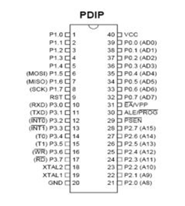
Configuration Pin Microcontroller AT89S51AT89S51 microcontroller pin arrangement shown in Figure 1.

https://pramonoteguh.files.wordpress.com/2013/12/pin.jpgFigure 1. Pin Configuration AT89s515. Functionality of Each Pin Microcontroller AT89S51Microcontroller AT89S51 has pins numbered 40 and generally packaged in DIP (Dual Inline Package). Each pin on the microcontroller AT89S51 have utility as follows:Port 0Port 0 is a function of two ports are on pins 32-39 of AT89S51. In the design of a simple system of this port as the port I / O versatile. For more complex designs involving this pathway dimultiplek external memory to the data bus and address bus.Port 1Port 1 is reserved as I / O ports and are on pins 1-8. Some pins on this port have special functions ie P1.5 (MOSI), P1.6 (MISO), P1.7 (SCK) is used to track the download program.Port 2Port 2 (pins 21-28) is a dual function as a port I / O versatile, or as high-byte address bus for design involving external memory.Port 3Port 3 is a two-port pin functions are at 10-17, this port has multiple functions, such as those found in table 1.1 below:ALTERNATE ADDRESS BIT BIT NAME FUNCTIONB0h P3.0 RXD Receive Data for serial portB1h P3.1 TXD Transmit Data for serial portB2h P3.2 INT0 External interrupt 0B3H P3.3 INT1 External interrupt 1B4h P3.4 T0 Timer / counter 0 external inputB5h P3.5 T1 Timer / counter 1 external inputP3.6 WR B6h External Data memory write strobeP3.7 RD B7h External Data memory read strobePSEN (Program Store Enable)Is an output signal that is contained in the pin 29. Its function is as a control signal to allow a microcontroller to read the program (code) of the external memory. Normally this pin is connected to pin EPROM. If the execution of the program from the internal ROM or flash memory (ATMEL AT89Sxx), then it is in the off state (high).ALE (Address Latch Enable)ALE output signal which is at pin 30, the same function with ALE in microprocessor INTEL 8085, 8088 or 8086. ALE signal is used to demultiplek address bus and a data bus. ALE signal generate pulses at 1/6 the oscillator frequency and can be used as a clock that can be used in general.EA (External Access)Input signals are on pins 31 which can be given a logic low (ground) or logic high (+ 5V). If given the high logic microcontroller will access the program from the internal ROM (EPROM / flash memory). If given a logic low, the microcontroller will access the program from an external memory.RST (Reset)Reset input on pin 9 is the master reset for AT89S51. Pulse transition from high to low during the second cycle will reset the microcontroller.OscillatorProvided on chip oscillator driven by XTAL connected to pin 18 and pin 19. Necessary stabilizing capacitor of 30 pF. Great value XTAL about 3 MHz to 33 MHz. XTAL1 is the input to a reversal of the oscillator amplifier (inverting oscillator amplifier) ​​and input to the internal clock operating circuit. While XTAL2 is the output of the oscillator amplifier reversal.PowerAT89s51 operated at a supply voltage of + 5V, Vcc pin is at number 40 and the Vss (ground) at pin 20.

Tuesday, September 15, 2015

Microcontroller AT89S51

Microcontroller type AT89S51 an MCS-51 microcontroller family with the exact same configuration with AT89C51 is quite well known, only AT89S51 features the ISP (In-System Programmable Flash Memory). This feature allows the microcontroller can be programmed directly into an electronic system without going through the Programmer Board or Board Downloader. The microcontroller can be programmed directly via ISP cable that is connected to the parallel port on a Personal Computer. As for the features of the microcontroller AT89S51 is as follows:

1. A CPU (Central Processing Unit) 8 bits including MCS51 family.2. The internal oscillator and timer circuit, 128 bytes of internal RAM (on-chip).3. Four Programmable I / O ports, each consisting of eight channels of I / O4. Two Timer Counter 16 bits.5. Five interrupt lines (2 external interrupt and internal interrupt 3)6. A serial port with full duplex UART serial control.7. The ability to carry out the operation of multiplication, division and Boolean operations (bit)8. Speed ​​instruction execution per cycle 1 microdetik at a clock frequency of 12 MHz9. 4 Kbytes of Flash ROM which can be filled and removed up to 1000 times10. In-System Programmable Flash MemoryWith the above feature, making the tool use AT89S51 to be more simple and does not require a lot of IC supporters. So the AT89S51 microcontroller has a privilege in terms of hardware.

Monday, September 14, 2015

Usefulness Microcontroller

Microcontroller has become common for use in a variety of areas, and can be found in household appliances, computer peripheral equipment and instrumentation. Microcontroller is also widely used in cars, many industries that use them, and have become a central part of the robotics industry. Because it is used to control a single process and execute the instructions are simple, mikorkontroler not require a large processing power.
The automotive market has been a key driver of the development of microcontrollers, many of which have been developed for automotive applications. Because microcontrollers used in automotive must face the harsh environmental conditions, they must be highly reliable and resilient. However, automotive microcontrollers, as well as other microcontrollers, is a product which is very cheap and can provide advanced features, without the encouragement of the development of the industry may be things that are not possible or would be very costly to implement.